

3D printing unlocks unequalled rapid prototyping opportunities but getting caught up in the iteration cycle creates bottlenecks.
With fewer iterations you can reduce time to final part and time to market, but it’s easier said than done with traditional, numerical workflow.
The traditional process sees engineers applying loads to already-manufactured parts and evaluating where they weaken. Engineers/designers then iterate parts to meet mechanical requirements, which eats up prototyping time.
Topology workflow is different – it uses software to propose the iterations with mathematical calculations. It starts with a 3D model, applies forces, and loads, and recommends iterations based on applied forces to automate this production process.
If that sounds as revolutionary as robot pickers in factories, that’s because it is, but it isn’t anything new – you just might not have heard of it.
This article reveals how topology optimisation creates new 3D printing opportunities and starts with the most critical question of all:
What is topology optimisation in 3D printing?
Topology refers to the perimeters of a 3D-printed object on all axes. Topology optimisation is a shape optimisation method that sees software use mathematics to find the most efficient placement of materials for parts.
Topology optimisation is helpful when designing parts because it can make them lighter, stiffer, and more robust while reducing material usage.
While replacing a plastic artist or engineer with a programmed algorithm sounds like it devalues their skillset, the opposite is true – it takes away the iteration grunt work. It frees up their time so they can focus on other things.
Topology optimisation benefits
- Reduce weight
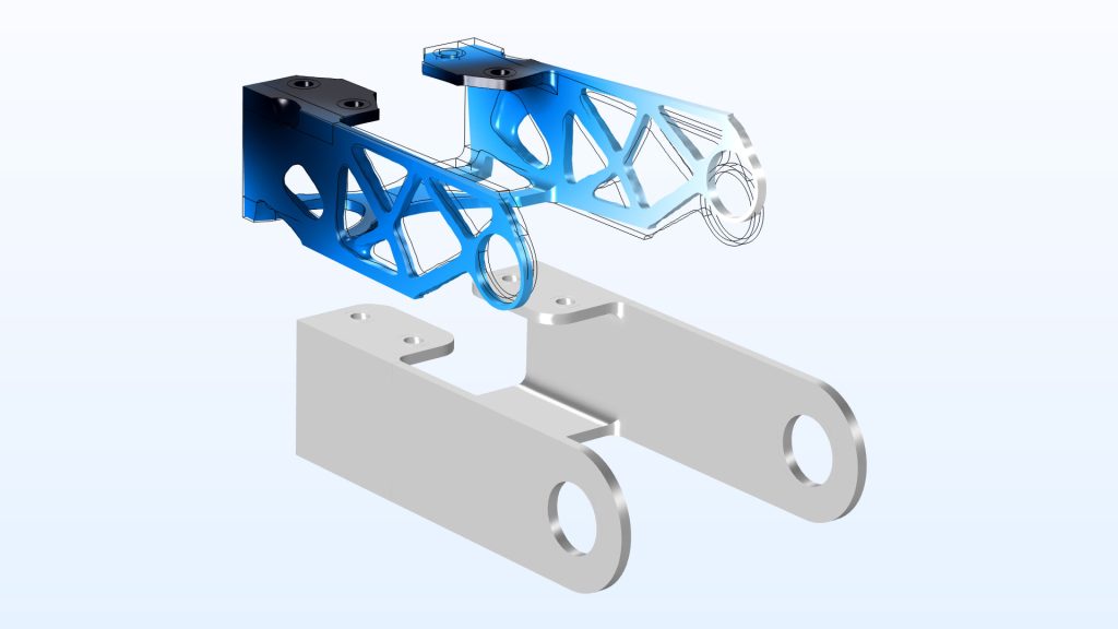
Topology optimisation strips out and replaces materials to reduce weight, identifying ways to make parts lighter without compromising other properties.
For example, General Electric used topology optimisation to reduce the weight of an engine bracket by 84%.
- Material reduction
Topology optimisation can reduce material usage by up to 40% by identifying more sustainable build paths. Material savings reduce the total cost per part and improve the sustainability of 3D printing workflows.
- Cost optimisation
Using mathematic calculations and AI, topology optimisation designs parts with the least amount of material, and you can configure it to use the fewest build paths. This lowers your material and development costs.
- Faster prototyping
Topology optimisation yields considerable time savings for rapid prototyping by replacing testing and guesswork with a computerised mathematical model. You can reduce your time to market while improving part quality.
Better performance
Topology optimisation can make parts lighter and improve their performance by identifying robust, stiffer, and more flexible build paths. Simply feed the software with desired outcomes, and it will do the rest.
Are there any limitations to topology optimisation?
The most significant limitation is that it can produce designs that 3D printers are incapable of producing, such as complex infills and surface details.
This is solved by choosing software with a manufacturing constraint feature and specifying the calculations the software can make.
Understanding what your 3D printing is capable of is also critical. If you have a new 3D printer or are producing parts with unfamiliar materials, it’s worth testing your printer, and you might also benefit from training.
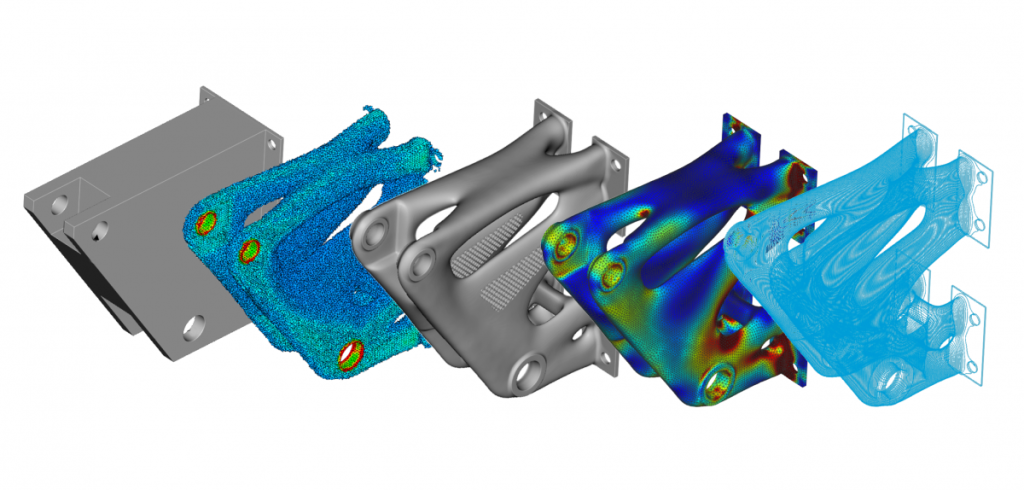
How does topology optimisation work?
Topology optimisation is a fully automated process run by CAD software. Human input is limited to designating the file, setting controls over calculations, and running simulations to find the most efficient build paths.

Although the calculations are automated, it’s crucial to note that you set how calculations are made regarding stress, objectives, gravity, and more.
These are some of the best-known topology optimisation programmes:
Although capability differences exist, the topology optimisation process is the same across all programmes. The most important thing is to define calculation settings to achieve optimal results.
Here’s a video showing how Altair Inspire works:
The process looks like this:
- Create a CAD model.
- Make a finite element method simulation (FEM) – This calculates stress distribution for loads and fixtures. Simply put, it is a computerised method for predicting how a product reacts to real-world forces.
- Create a finite element mesh – This transforms your solid model into a polygonal mesh that software can crunch with mathematics.
- Optimisation preparation – Select the settings that control optimisation calculations. Your choices create constraints with symmetries, mass, and more. The settings you have at your disposal also depend on which software you use.
- Run optimisation study – Let the software optimise the model based on your settings.
- Remodel for manufacturability – Once you have the study, you must consider what you can replicate with your 3D printer. Note that topology recommendations are hardware dependent.
Who should use topology optimisation?
Topology optimisation works best for precision applications rather than generic model-making to improve development times significantly.
For example, Preziosa Francesco SRL, an Italian sheet metal manufacturer, deployed nTopology software and 3D printing to replace CNC machining, producing robot grippers from design to application in four days.
In another example, SolidWorks topology optimisation helped optimise the weight of housings for spur gear reducers, reducing weight by 7.33%.
Topology optimisation is a faster approach to design, a process that hurdles iterative bottlenecks while improving part performance.
Producing optimal 3D printed geometries is easier with topology optimisation, and we have no doubt it will explode in popularity in technical industries in the next decade.
Find out more
If you enjoyed this article, read our piece on the different types of filaments.
For expert advice on topology optimisation and 3D modelling, please get in touch with the team at 01765 694 007, email [email protected], or you can
 Book an appointment with Elaine
Top image credit: Formlabs