

Many factors determine the accuracy and surface finish of 3D printed parts, but part orientation is up there with the most important.
Part orientation refers to how you print parts on the build platform, which dictates the print head’s travel.
The cusp of it is that FFF 3D printers produce parts with anisotropic properties where the X, Y, and Z axes’ values differ with the part’s orientation.
Orientation impacts print accuracy, surface quality, and print time, so it’s worth knowing the best orientation per model.
This article explores the main effects of part orientation on 3D printed parts with expert tips to help you get the most out of your 3D printer.
Let’s jump in!
What is part orientation?
Part orientation (or build orientation) defines how a 3D-printed part contacts the build plate. The simple question is, which way down?
There are several factors to consider for optimal part orientation:
- Stability and bed adhesion. Identify the part faces that require adhesion to the build plate.
- Mechanical stresses. Identifying part faces that will experience stress to orientate in ways that minimise it.
- Build volume. Ensure that orientation is within the building capacity of the 3D printer.
- Print times (speed). Find a balance between print speeds and stability to ensure maximum uptime and printer utilisation.
- Support requirements. Look for ways to minimise support requirements to reduce complexity and material usage.
- Post-processing requirements. How will part orientation impact post-processing? Can orientation reduce post-processing times?
Now that you know the factors that determine optimal orientation, here are the most significant effects on 3D-printed parts:
Effect #1 – Accuracy
Part orientation defines how the print head moves to build a part, including the direction of travel between layers, which in turn defines the shape of the layers.
All FFF/FDM 3D printed parts have visible layer lines, but an improperly orientated part’s layers are more visible.
Take this cylinder as an example:

The left cylinder was printed with a vertical centre axis, while the one on the right was printed with a horizontal centre axis.
The first cylinder has a smooth surface, while the second has a rough surface – simply put, the second cylinder is less accurate. This is because the first was printed with circular layers and the second with rectangular layers.
Effect #2 – Print time (speed)
Not only does part orientation affect print accuracy by changing layer patterns, but it also alters print speed by reducing or increasing the layers required.
For example, the left cylinder in the picture above has three times fewer layers than the one on the right – it is printed at 100 μm, while the right cylinder is at 300 μm.
More layers equal a slower print speed, so proper part orientation can reduce print times to speed up your workflow and increase uptime.
Additionally, fewer layers equal less material usage – win-win!
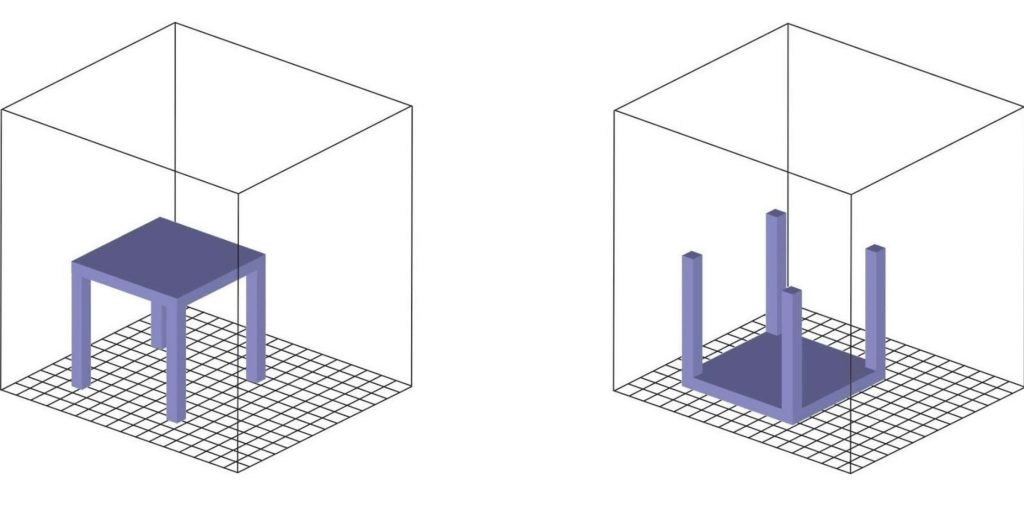
Effect #3 – Part strength
FFF/FDM 3D printers produce parts with anisotropic properties, meaning they are more robust in the X-Y direction than the Z direction. However, you can close the gap to increase strength with proper orientation.
The critical thing to know is that tension load down on layers exposes weakness, while tension load parallel to layers showcases strength.
If you need parts to withstand mechanical stresses in the X, Y, or Z directions, you must orient parts to account for the direction of loads. The vertical build layer is the weakest, so you might best orient horizontally.
Effect #4 – Support structures
One of the biggest mistakes when designing parts is producing support structures that are avoidable with proper part orientation.
Support structures often are a by-product of poor orientation, introducing complexity that shouldn’t be present in relatively simple parts.
Orientating in the correct build direction can eliminate the requirement for support structures and, in turn, increase print speed and reduce part complexity.
For example, you can orient so that overhangs of less than 45° are minimised – this will strip away the requirement for supports if you use a rigid material.
Effect #5 – Surface finish (surface quality)
The surface finish of 3D-printed parts is affected by orientation in a few ways.
The most obvious thing is that the surface in contact with the build plate is smooth with a glass or metal build plate.
Additionally, the top or upward-facing features are smoothed by the extrusion tip. You can change part orientation to minimise these effects.
With SLA 3D printers, the lower surfaces have support marks unless you use the Formlabs Form 3/3L/3B, which uses a proprietary technology called Low Force Stereolithography which reduces the peel forces on 3D printed parts.
Effect #6 – Print costs
Part orientation affects print speeds and material usage, so it has two effects on print costs – time and physical resources.
Incorrect orientation can increase the number of layers and supports required to build a part and, in turn, the total print time. As you scale and print more parts, these costs and time inefficiencies soon increase.
Another factor to consider is that improper build orientation can increase mechanical stress on parts on the build platform, increasing the risk of print failure. Every failure will go in the recycling bin unless you can repurpose the plastic.
Is it better to 3D print vertically or horizontally?
All this boils down to whether you should orientate vertically or horizontally for optimal performance and efficiency.
We recommend orienting vertically for cylindrical models and features and horizontally for everything else. This is because horizontal orientation is faster and increases strength, except for cylindrical models.
Find out more
If you enjoyed this article, read our piece on the different types of filaments.
For expert advice on part orientation, please get in touch with the team at 01765 694 007, email [email protected], or you can
 Book an appointment with Elaine
Top image credit: Innovation Labs.